Creo Sheet Metal Lance

Introduction To Drawings In Creo Parametric 2 0 Parametric Solidworks Getting Things Done

Advanced Modeling In Creo 3d Model Mechanical Design Model

Learn Creating Complex 3d Models Solidworks Interview Tool Test Solidworks Tutorial Solidworks 3d Model

Sw 3d Modeling Practice 3d Modeling Tutorial Technical Drawing Autocad Drawing
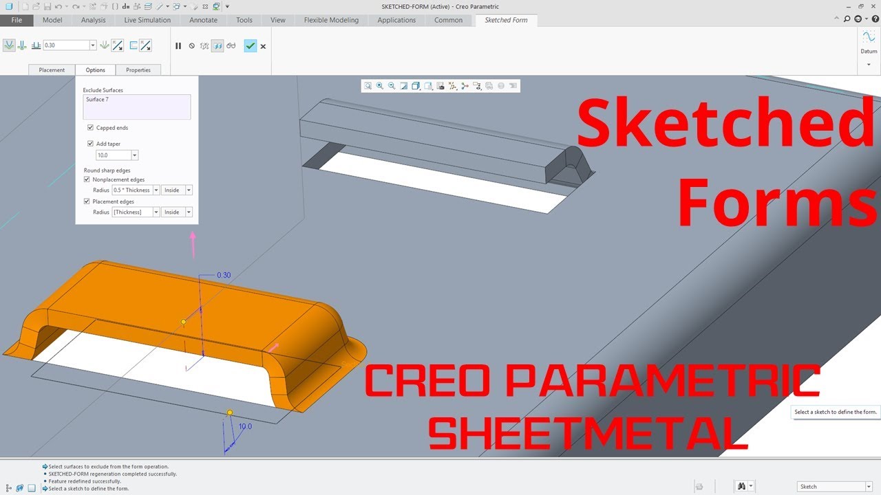
Creo Parametric Sheetmetal Sketched Forms Tutorial Youtube

Belt Chain For Conveyor In Solidworks Youtube Solidworks Conveyor Videos Tutorial

The die form workflows and user interface have been enhanced and modernized in ptc creo 3 0 so they are consistent with those of the punch form tool.
Creo sheet metal lance.

Punch Form Features Ptc Learning Connector

Pin On Laser

Pin On Mechanical Cad Services
Create Stamp Features With Stamp Tools
Source : pinterest.com
