Creo 2 Fillet Sheet Metal Corner

Fillet In Solidworks By Smart Corner بالعربي Solidworks Corner Smart

Solidworks Advanced Fillet Corner Quick Tip Youtube

Solidworks Sheetmetal Close Corner Weld Corner Corner Relief Chamfer Fillet Hindi Urdu Youtube

Autodesk Inventor Tutorial For Beginners Exercise 7 Youtube Autodesk Inventor Autodesk Inventor
Pulling Walls

Solidworks Tutorial For Beginners Exercise 25 Youtube Solidworks Tutorial Solidworks Tutorial

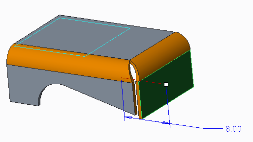
5 create a new flange 4 see that the bend is not nice the green circle how can i make the two red corners together.
Creo 2 fillet sheet metal corner.

Gusset In Solidworks Sheet Metal Design Tutorial 13 Youtube

Solidworks Tutorial For Beginners Exercise 65 Youtube Solidworks Tutorial Solidworks Technical Drawing

How To Create Fillets With Variable Radius Solidworks Tutorials Solidworks Tutorial Solidworks Tutorial

Solidworks Advanced Tutorial Exercise 83 Youtube Solidworks Technical Drawing Tutorial
Source : pinterest.com
